System Failover Architecture
System failover architecture defines how a system automatically detects the failure of a primary component and promotes a standby replacement to restore service — minimizing the recovery time objective (RTO) without manual intervention.
System failover architecture defines how a system automatically detects the failure of a primary component and promotes a standby replacement to restore service — minimizing the recovery time objective (RTO) without manual intervention.
What the diagram shows
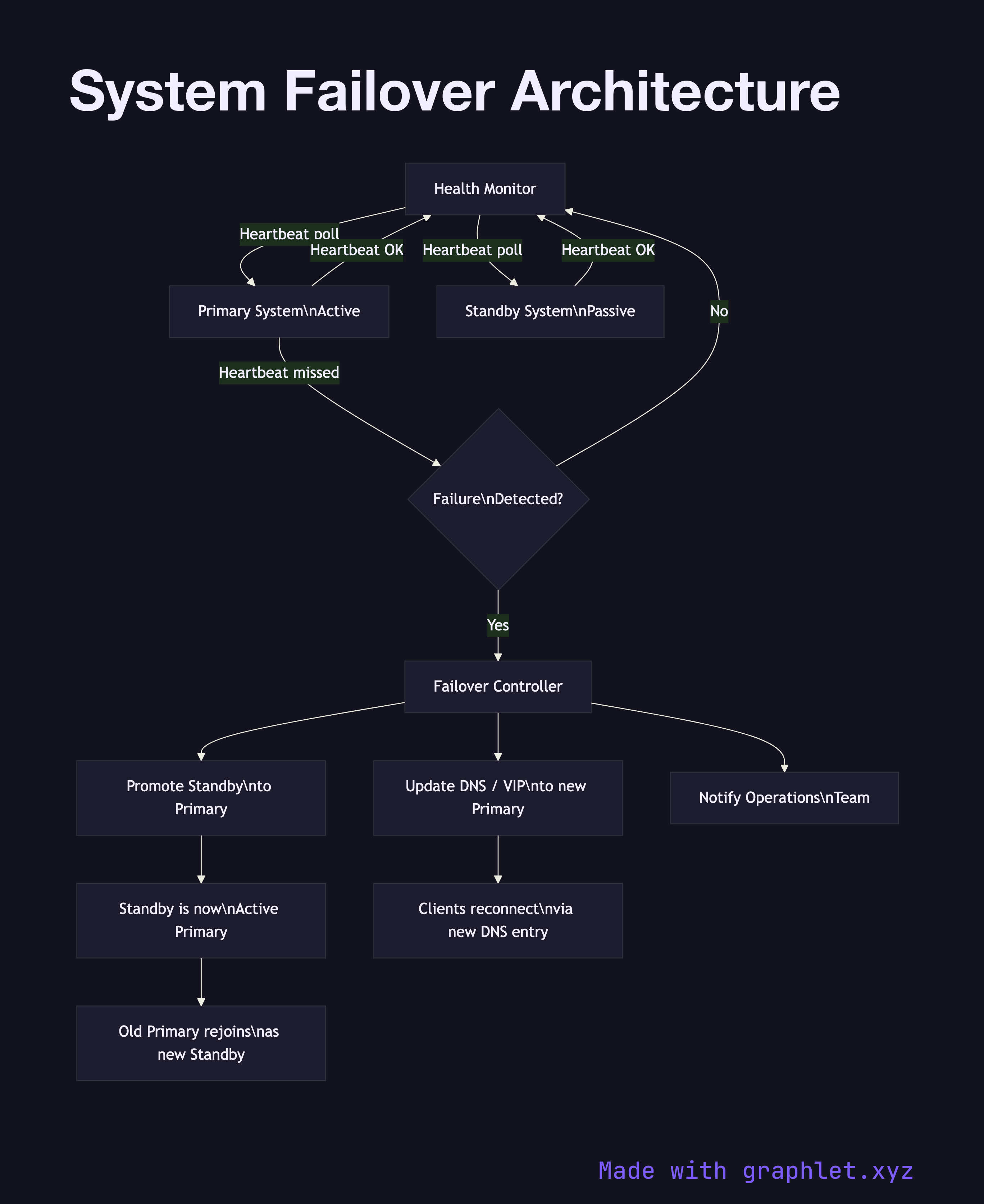
The diagram shows a Health Monitor continuously polling both the Primary System and the Standby System via heartbeat checks. When the Primary fails, the Health Monitor detects the missed heartbeats and triggers the Failover Controller. The controller performs three sequential steps: it promotes the Standby to Primary, updates the DNS / VIP (virtual IP) record to point to the newly promoted instance, and notifies the Operations Team via an alerting channel.
Clients that had connections to the old primary experience a brief interruption equal to the DNS TTL or VIP switchover time (typically seconds). Once DNS propagates, new connections route to the promoted instance. The old primary, if it recovers, rejoins as the new standby rather than automatically reclaiming primary status (to avoid split-brain scenarios).
Why this matters
Automated failover is essential for meeting SLA targets above 99.9% uptime. Manual failover — where an on-call engineer must log in and reconfigure routing — introduces human response time into the recovery window, easily adding 5–30 minutes of downtime. The diagram makes the monitoring and decision path explicit, which is useful for designing health check intervals, TTL values, and alerting thresholds. For the broader HA architecture this sits within, see High Availability System. For cross-region failover, see Multi Region Deployment.