diagram.mmd — flowchart
Scalable Web Architecture flowchart diagram

A scalable web architecture is designed to handle increasing user load by distributing traffic, caching aggressively, and separating stateless compute from stateful storage so each tier can scale independently.

What the diagram shows

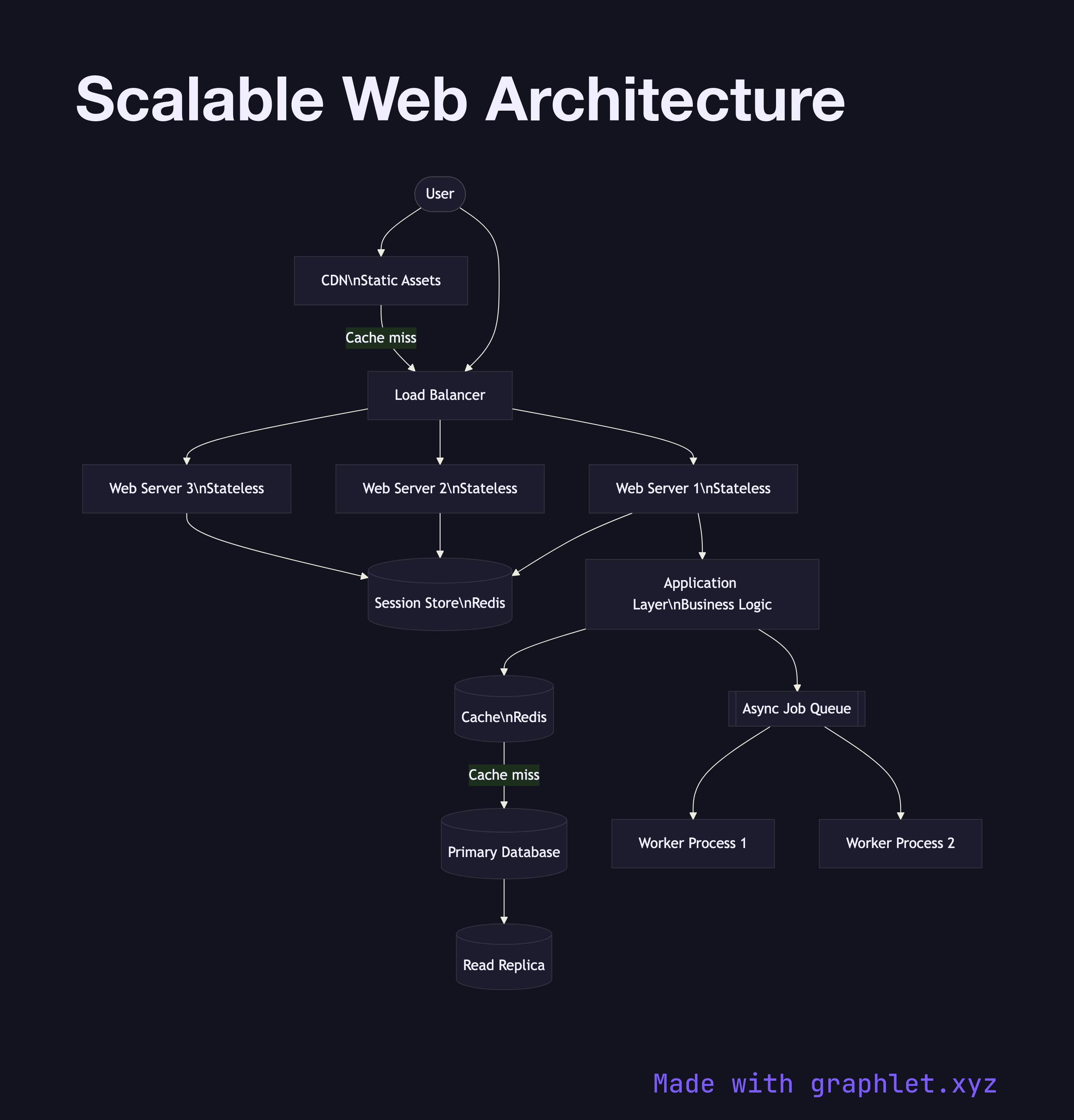
Requests arrive at a CDN (Content Delivery Network), which serves static assets — images, CSS, JavaScript — from edge nodes close to the user without touching the origin. Dynamic requests pass through to a Load Balancer, which distributes them across a pool of Stateless Web Servers. Because session state is stored externally in a Session Store (Redis), any web server can handle any request, making horizontal scaling straightforward.

The web servers call an Application Layer (business logic), which reads from a Cache before querying the Primary Database. The primary replicates to one or more Read Replicas to spread read load. Heavy background workloads — report generation, email delivery, data exports — are pushed onto an Async Job Queue consumed by Worker Processes that run independently of the request path.

Why this matters

The key principle is isolating stateful components (databases, caches) from stateless ones (web servers, workers). Stateless components can be cloned freely behind a load balancer; stateful components require replication or partitioning strategies. Adding a CDN alone can eliminate 80–90% of origin traffic for content-heavy applications. For high availability across failures, see High Availability System. For multi-region extension of this pattern, see Multi Region Deployment.

Free online editor
Edit this diagram in Graphlet
Fork, modify, and export to SVG or PNG. No sign-up required.
Open in Graphlet →

Frequently asked questions

A scalable web architecture is designed to handle growing user load by distributing traffic across stateless servers, caching aggressively at multiple layers, offloading heavy work to async queues, and separating stateless compute from stateful storage so each tier can scale independently.
A CDN intercepts static asset requests at the edge, reducing origin load by 80–90%. A load balancer distributes dynamic requests across stateless web servers that read session state from a shared store. Application servers check a cache before querying the primary database; read replicas handle query scale-out. Background jobs are queued and processed by independent worker processes.
Begin planning for scalability when your single-server deployment starts showing signs of bottleneck — high database CPU, slow page loads under peak traffic, or session state that prevents horizontal scaling. Many of the patterns (CDN, caching, async queues) add value from day one even at small scale.
Common mistakes include storing session state in-process (preventing horizontal scaling), querying the database on every request for data that rarely changes (solvable with caching), and running long synchronous tasks in the request thread (solvable with async queues) — all of which limit the ability to scale horizontally.
mermaid
flowchart TD User([User]) --> CDN[CDN\nStatic Assets] User --> LB[Load Balancer] CDN -->|Cache miss| LB LB --> WS1[Web Server 1\nStateless] LB --> WS2[Web Server 2\nStateless] LB --> WS3[Web Server 3\nStateless] WS1 --> Sessions[(Session Store\nRedis)] WS2 --> Sessions WS3 --> Sessions WS1 --> AppLayer[Application Layer\nBusiness Logic] AppLayer --> Cache[(Cache\nRedis)] Cache -->|Cache miss| PrimaryDB[(Primary Database)] PrimaryDB --> ReadReplica[(Read Replica)] AppLayer --> JobQueue[[Async Job Queue]] JobQueue --> Worker1[Worker Process 1] JobQueue --> Worker2[Worker Process 2]
Copied to clipboard