IP Packet Routing
IP packet routing is the process by which routers examine a packet's destination IP address and forward it hop-by-hop through the network toward its destination, using routing tables to make forwarding decisions at each hop.
IP packet routing is the process by which routers examine a packet's destination IP address and forward it hop-by-hop through the network toward its destination, using routing tables to make forwarding decisions at each hop.
IP (Internet Protocol) is connectionless and stateless: each packet is forwarded independently, and routers hold no per-flow state. This design makes the internet robust — packets can take different paths, and routing dynamically adapts to failures.
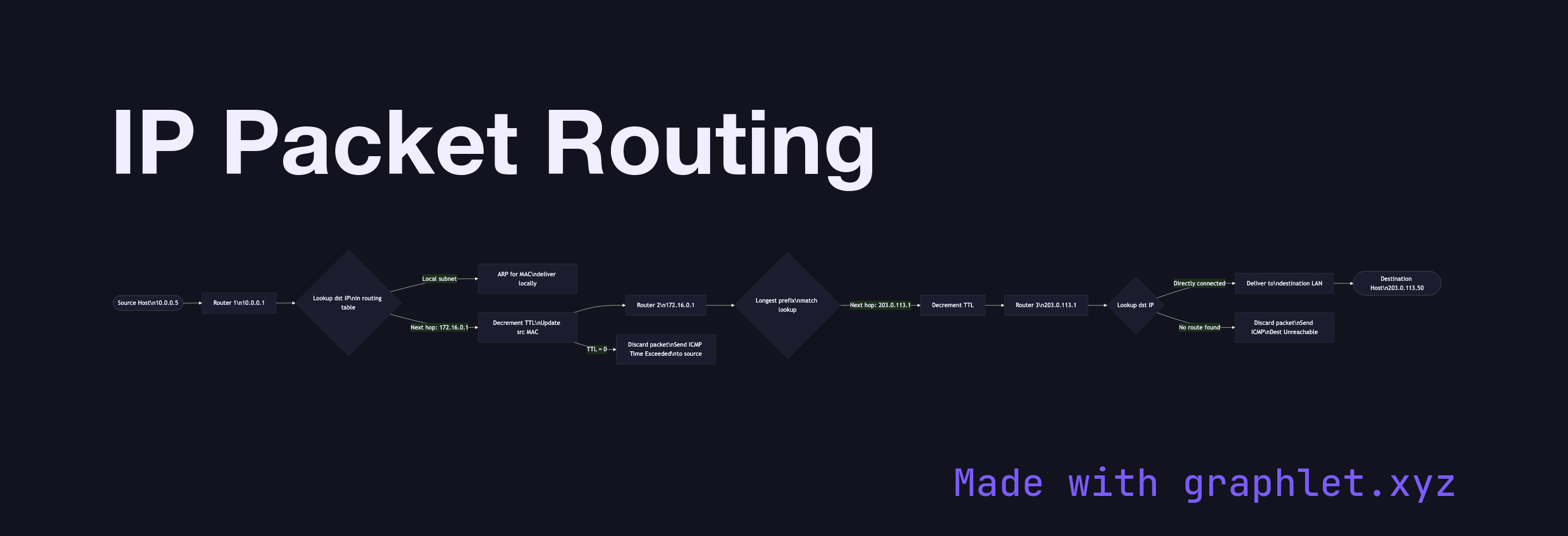
Routing Table Lookup: Each router maintains a routing table — a set of prefix-to-next-hop mappings. When a packet arrives, the router performs a longest prefix match: it finds the most specific routing table entry whose prefix contains the destination IP. The matched entry specifies the next-hop IP and outgoing interface.
Local Delivery vs. Forwarding: If the destination IP is on a directly connected subnet, the router delivers the packet locally (using ARP to find the MAC address; see ARP Resolution). Otherwise, it forwards to the next-hop router, decrementing the IP TTL field by 1.
TTL and Loop Prevention: The TTL (Time to Live) field is decremented at each hop. If TTL reaches 0, the packet is discarded and an ICMP "Time Exceeded" message is sent back to the source. This prevents packets from circling the network indefinitely. Traceroute exploits this behavior to map network paths.
Routing Protocols: Routing tables are built dynamically by protocols like OSPF (within an AS) and BGP (between autonomous systems). BGP is the "glue" of the internet, enabling anycast routing and inter-domain traffic engineering.
Fragmentation: If a packet exceeds the MTU of the outgoing link, IPv4 routers may fragment it (IPv6 requires the source to handle fragmentation). See Packet Fragmentation.