diagram.mmd — flowchart
OSI Layer Interaction flowchart diagram

The OSI (Open Systems Interconnection) model is a conceptual framework that describes how network communication is structured into seven distinct layers, each responsible for a specific aspect of data transmission, with each layer adding its own header during encapsulation.

The OSI model was developed by ISO in the 1980s as a standardization framework. While the actual internet runs on the TCP/IP model (which merges several OSI layers), OSI remains the universal reference model used to reason about network protocols, troubleshoot issues, and describe where specific technologies operate.

The Seven Layers (top to bottom):

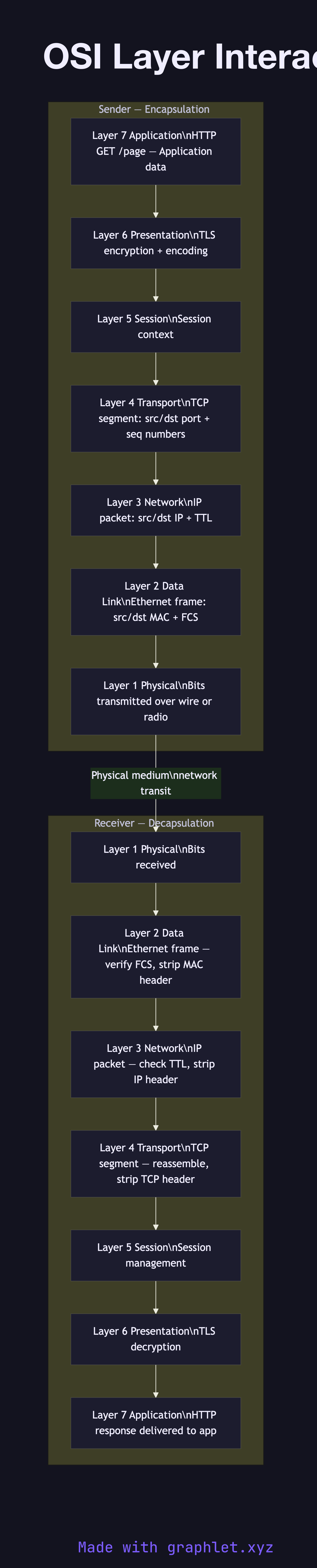
- Layer 7 — Application: The protocol the application uses: HTTP, DNS, SMTP, FTP. This is what developers typically interact with. - Layer 6 — Presentation: Data encoding, compression, encryption. TLS/SSL operates here — encrypting application data before transport. - Layer 5 — Session: Session management, dialog control. TCP session establishment maps loosely here. - Layer 4 — Transport: TCP and UDP. Handles segmentation, reliability (TCP), and port addressing. - Layer 3 — Network: IP. Logical addressing and routing. Routers operate at this layer. - Layer 2 — Data Link: Ethernet, WiFi. MAC addressing and frame delivery on a local segment. Switches operate here. - Layer 1 — Physical: Cables, radio waves, optical fiber. Raw bit transmission.

Encapsulation: As data moves down the stack on the sender, each layer adds its own header (and sometimes trailer). At the receiver, each layer strips its header as data moves up. This is why protocols are described as "running over" lower layers: HTTP runs over TCP runs over IP runs over Ethernet.

The TLS Handshake operates at Layer 6/4, TCP Three-Way Handshake at Layer 4, and ARP at Layer 2.

Free online editor
Edit this diagram in Graphlet
Fork, modify, and export to SVG or PNG. No sign-up required.
Open in Graphlet →

Frequently asked questions

The OSI (Open Systems Interconnection) model is a conceptual framework developed by ISO that describes network communication as seven distinct layers, from physical bit transmission at Layer 1 up to application protocols at Layer 7. It provides a common vocabulary for describing where technologies and protocols operate in the networking stack.
Layer 1 (Physical) transmits raw bits over cables, fiber, or radio. Layer 2 (Data Link) handles MAC addressing and frame delivery on a segment. Layer 3 (Network) manages IP addressing and packet routing. Layer 4 (Transport) provides TCP/UDP with ports, reliability, and flow control. Layer 5 (Session) manages session establishment. Layer 6 (Presentation) handles encoding and encryption (TLS). Layer 7 (Application) is the user-facing protocol: HTTP, DNS, SMTP.
As data moves down the sender's stack, each layer adds its own header (and sometimes trailer) to the data it receives from the layer above. HTTP data gets a TCP header at Layer 4, then an IP header at Layer 3, then an Ethernet frame header at Layer 2. The receiver strips each header moving up the stack. This is why protocols are described as "running over" lower layers.
The TCP/IP model (also called the Internet model) has four layers and reflects how the actual internet is built: Network Access (merges OSI Layers 1–2), Internet (OSI Layer 3), Transport (OSI Layer 4), and Application (merges OSI Layers 5–7). The OSI model is more granular and is used as a teaching and reference framework, while TCP/IP describes the real-world protocol stack.
mermaid
flowchart TD subgraph Sender ["Sender — Encapsulation (top to bottom)"] L7S[Layer 7 Application\nHTTP GET /page — Application data] L6S[Layer 6 Presentation\nTLS encryption + encoding] L5S[Layer 5 Session\nSession context] L4S[Layer 4 Transport\nTCP segment: src/dst port + seq numbers] L3S[Layer 3 Network\nIP packet: src/dst IP + TTL] L2S[Layer 2 Data Link\nEthernet frame: src/dst MAC + FCS] L1S[Layer 1 Physical\nBits transmitted over wire or radio] end subgraph Receiver ["Receiver — Decapsulation (bottom to top)"] L1R[Layer 1 Physical\nBits received] L2R[Layer 2 Data Link\nEthernet frame — verify FCS, strip MAC header] L3R[Layer 3 Network\nIP packet — check TTL, strip IP header] L4R[Layer 4 Transport\nTCP segment — reassemble, strip TCP header] L5R[Layer 5 Session\nSession management] L6R[Layer 6 Presentation\nTLS decryption] L7R[Layer 7 Application\nHTTP response delivered to app] end L7S --> L6S --> L5S --> L4S --> L3S --> L2S --> L1S L1S -->|Physical medium\nnetwork transit| L1R L1R --> L2R --> L3R --> L4R --> L5R --> L6R --> L7R
Copied to clipboard